GASEXIT RUNNER
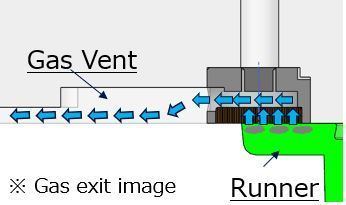
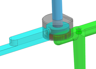
GASEXIT RUNNER is an insert that discharges gases laterally between the P/L surface and the plate.
【Patent No. 6664721】
Given that it is only a Φ10~Φ15 machining on pockets and grooves, it is a low-cost, easy-to-use Mold Venting measure for existing dies.
GASEXIT RUNNER features
Gases venting are 15 to 20 times higher!
The gases vent machined in the normal runner end has a hollow dept of about 0.02 mm, so almost no gases can be released.
By installing the GASEXIT RUNNER will overlap the runner end, so gases will escape from the overlaped area.
The area through which gases escape is increased from 15 to 20 times than that of a normal gases vent.
Withstand a 20,000N load
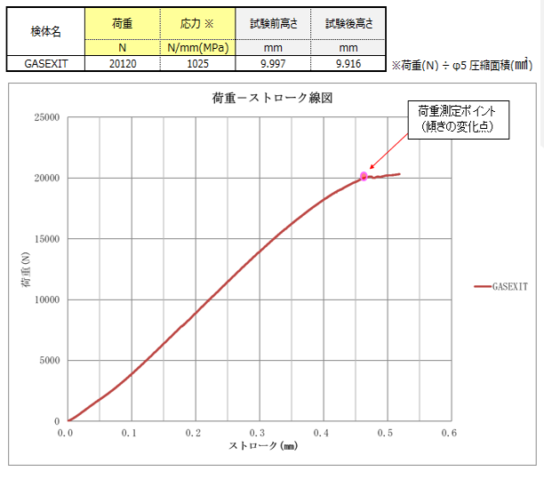
The result of a compression test using a GASEXIT RUNNERof Φ12 mm and a rod of Φ5 mm, has confirmed that it can withstand a load of 20,000 N .
Therefore, there is no concern about buckling due to resin pressure.
Supports large molds
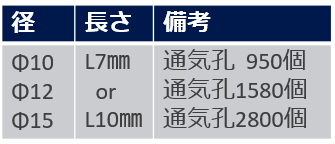
We have three sizes, Φ10, Φ12, and Φ15.
The Φ15 can be used for large molds with large runner sizes.
Since the minimum thickness is 7 mm, when adding GASEXIT RUNNER to a mold Which is already in mass production, the size is set so that it will not interfere with the mold temperature control water pipe.
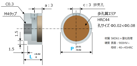
GASEXIT RUNNER仕様
Installation method
Installation method
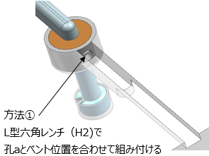
①Positioning using a Hex wrench
1. Insert the L-shaped hex wrench (H2) into the exhaust port of the GAS EXIT RUNNER
2. Align the direction of the hex wrench (exhaust port of the GASEXIT RUNNER) with the direction of the gas vent groove and insert it in the pocket
3. Fixed with a M4 tap
※Not required if it has been press-fitted fixed
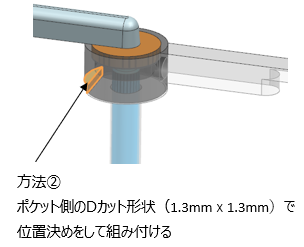
②Positioning method using D-cut shape
1. A 1.3 mm x 1.3 mm D-cut shape that is perpendicular to the gas vent groove is machined on the mold base side.
2. Align the D-cut direction on the GASEXIT RUNNER side with the D-cut shape on the mold base side and insert it into the pocket
3. Fixed with a M4 tap
※Not required if it has been press-fitted fixed
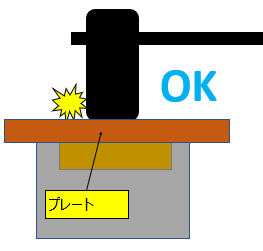
Precautions
1. If you hit the center of the GASEXIT RUNNER, it may be deformed, so if you hit it when inserting it, please pinch the plate.
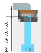
2. Adjust the length of the tap so that the M4 tap does not hit the bottom of the GASEXIT exhaust side and the tip of the tap comes to a position of 3.0 mm to 5.0 mm from the surface.
Mold base side gas vent machining details
1. Please machine the pocket according to the external shape and depth of the GAS EXIT RUNNER you purchased.
※The pocket should be machined so that the runner edge and the GASEXIT porous part overlap as much as possible.
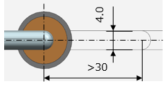
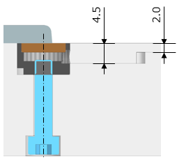
2. Machine a gas vent groove with a depth of 4.5 mm x a width of 4.0 mm x a length of 30 mm or more
※When fixing the position with a D-cut shape, It is possible to have a groove length of 30 mm or less
3. Please machine the gas vent groove to a depth of 2.0 mm x a width of 4.0 mm to the outside of the mold base.
※If the groove depth is shallow, it may not be possible to exhaust gas sufficiently.
Example of a real usage of GASEXIT RUNNER
Reduction of silver streak defects while also wanting to reduce maintenance frequency
【Problem】
・5.0% of silver streak defects are occuring
・It is possible to reduce the defect rate to 5.0% or less by shortening the mold maintenance cycle, but it is fixed up to 10,000 shots due to man-hours.
※Material:ABS
【Countermasure】
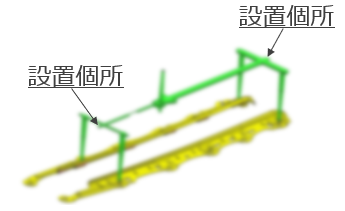
Install 2 GAS EXIT RUNNER at the edge of the runner
【Results】
1. The defect rate has been reduced from 5.0% to 0.2%
2. Since the mold deposit is less likely to adhere to the ejector pins, the maintenance cycle is extended from 10,000 shots to 40,000 shots.
3. Kaizen effect ¥86,500/month
Would you like to try it?
Therefore, our product GAS EXIT RUNNER can reduce molding defects caused by gases and extend the mold maintenance cycle.
If you are interested in GASEXIT RUNNER, please feel free to iquire or contact us.
お問合せはこちら

お電話でのお問合せ・ご相談
フォームでのお問合せは24時間受け付けております。お気軽にご連絡ください。
ソリューションアシスト株式会社